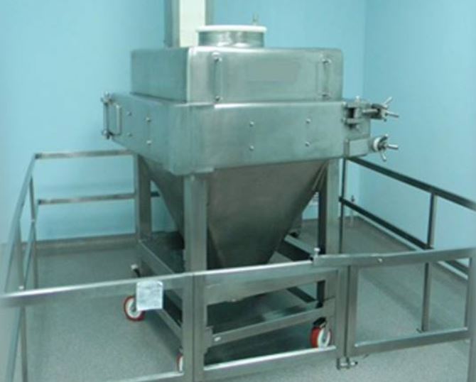
Qualification is the process of planning, conducting, and recording tests on equipment and systems that will be used in a validated process to ensure that they will work as expected. The bin blender’s (200 L) performance qualification for minimal (20%) and maximum (70%) occupancy capacities, as well as blend uniformity at various blending time intervals.

Bin Blender Design Qualification Steps:
- Objective
- Scope
- Responsibility (Client and manufacturer)
- URS (User Requirement Specification)
- Machine description
- Technical specification
- Technical specifications of the sub-components/bought-out items, and their make, model & quantity, and backup records/ brochures
- Details of Utilities
- Identification of components for calibration
- Material of construction of all components
- P & ID diagrams for reference & approval
- Equipment orientation with room layout
- Brief process description
- Safety features and alarms
- FAT procedure
- Change control procedure
- Qualification Document report approval
- Appendix
1.0 OBJECTIVE:
To design, engineer, and supply the Blender Bin (Model: RP/BUK/1200Ltrs.) as per cGMP and cGEP guidelines and to provide assurance that the machine is manufactured as per the complies with the Scope of Supply.
To prove that each operation proceeds as per the design specification and the tolerances prescribed there in the document are the same at utmost transparency. The validation procedure is set for the complete satisfaction of the customer & building the confidence of the user about the machine.
2.0 SCOPE:
The scope of this qualification document is limited to the Design Qualification of Blender Bin (Model: RP/BUK/1200Ltrs.) This qualification document is part of a validation activity for the Blender Bin (Model: RP/BUK/1200Ltrs.)
The scope of this qualification document does not include support utilities.
The Blender Bin shall be used for Mixing/Blending powders/granules. to be used in the Pharmaceutical formulation and also as an in-process container.
3.0 RESPONSIBILITIES:
CLIENT
- To provide the URS for the equipment.
- To perform the Factory Acceptance Test (FAT).
MANUFACTURER:
1. To design, engineer, and give all technical data relevant to the equipment’s design qualification, i.e.
- Machine overview,
- P&ID drawing,
- Equipment orientation with layout,
- Specifications of the sub-components/bought-out items, and their make, model & quantity, and backup records/ brochures,
- Details of Utilities,
- Identification of components for calibration
- Material of construction of all components
- Brief process description
- Safety features and alarms
- Pre-installation requirements
2. To make it easier for the client to perform the factory acceptance test of the equipment at their workplace or location.
3. To ensure the safe delivery of the equipment/ machine to the user site.
4. To ensure that no unauthorized and/or unrecorded design modifications shall take place. If at any point in time, any change is desired in the mutually agreed design, the Change control procedure shall be followed and documented.
5. To ensure the proper installation and commissioning of the equipment.
4.0 USER REQUIREMENTS SPECIFICATION (URS):
| DESCRIPTION | SPECIFICATIONS |
| Equipment | Blender Bin |
| Specification | SS 316L Blender Bin with Butterfly valve, vent & trolley on wheels. |
| Capacity | 1200Ltrs. |
| Model | RP/BUK/1200Ltrs.The equipment should be a cGMP model, compliant with contract-specific SS316L parts. The Bin will be provided with a loose SS 304 Trolley with PU-coated castor wheels. |
| Process | The bin should be able to perform solid to solid mixing efficiently with the help of the Blender. |
| Material of construction | Bin, Lid & Butterfly Valve – SS 316L Gasket – Food grade silicon Rubber. Wheel bracket & Trolley – SS 304. Castor wheels – PU Coated Nylon |
| DESCRIPTION | SPECIFICATIONS |
| Calibration | Not Applicable. |
| Qualifications/ Documentation | The manufacturer shall complete and provide the documents pertaining to Design, Installation & Operation Qualification, and detailed functional specifications. Information on purchased/bought-out parts. Alarms & Interlocks. Information on purchased/bought-out parts. Circuits & interlocks details. |
| Safety features | Adequate safety features for men and materials shall be provided along with the equipment. Non-Flameproof motors and controls. |
| Control system | The equipment shall be controlled manually through the Main Panel and control Panel. The Control panel carries UP & DOWN push buttons for lifting & lowering the load and MMI for Blender operation. |
| Electrical system | The electrical system of the equipment shall be housed as per the cGMP and cGEP standards, with adequate safety The Electrical Control panel is to be installed on the wall in the production area & main panel in the technical area on top of the ceiling. |
5.0 MACHINE DESCRIPTION:
5.1 Process Equipment Description
The purpose of the container Blender is to mix various substances in dry powder and / Or granular form. Mixing can be achieved by selecting a suitable RPM and suitable time periods depending on the product characteristic. The following setting can be done in the VFD:-
- RPM setting
- Soft start
- Soft stop
The complete machine can be divided into the following sub-sections:
- Drive shaft with bearing housing
- Speed reduction system consisting of Brake Motor & Worm & Worm Wheel reduction gearbox Gear – Pinion arrangement.
- Container holding arm.
- Hydraulic power pack & cylinder.
- Main electric panel (housing PLC, VFD) & safety railing with operating panel (having MMI, Push buttons).
6.0 TECHNICAL SPECIFICATIONS:
- Blender Bin – SS 316L x 3mm Thk.
- Lid – Hinged with Gasket 350dia., SS 316L
- Butterfly Valve – SS 316L with Gasket, 190dia.
- Trolley – SS 304 2” dia x 10G. Pipe and 610mm dia x 10G Pipe ht: 775 mm with wheels.
- Trolley Castor wheels – SS 304 Bracket, PU PU-coated nylon wheels 6” x 2” W, 2 Fixed & 2 swivel types.
- Gaskets & Valve Seat – Food Grade Silicon.
6.1 Operating Control Panel
Not Applicable.
6.2 Main Electric Panel
Not Applicable.
6.3 Spares
- Butterfly Valve Seat (190 dia) 1No.
- Butterfly Valve Flange Gasket (190 dia) 2Nos.
- Castor wheel 6”dia x 2” (w) Swivel 2Nos.
- Castor wheel 6”dia x 2” (w) Fixed 2Nos.
- “O” ring for 350dia Lid 2Nos.
7.0 TECHNICAL SPECIFICATIONS OF COMPONENTS & SUB –
COMPONENTS USED / BOUGHT OUTS
| S.No. | DESCRIPTION | SPECIFICATIONS |
| 1. Equipment Description | ||
| Name | Blender Bin | |
| Specification | Suitable for 1200Ltrs. Blender with Butterfly Valve & Trolley | |
| Capacity | 1200Ltrs. | |
| Model | RP/BUK/1200Ltrs. | |
| Overall dimensions | See drag MAC – BUK – 4251-00. | |
| Weight | ||
| Surface Finish | Matt Finish (Grit 180) outside, Mirror finish – inside 320 Grit. | |
| Foundation Bolts | NA | |
| 2. PLC:- NOT APPLICABLE | ||
| 3. MMI:- NOT APPLICABLE | ||
| 4. Power Pack:- NOT APPLICABLE |
8.0 MATERIAL OF CONSTRUCTION
- Bin SS 316L
- Trolley SS304.
- Castor wheel PU Coated Nylon.
- Gasket Food Grade Silicon
9.0 P & ID DIAGRAM FOR REFERENCE & APPROVAL
Attached as annexure – DQ/ANX/IV (Drg. MAC – BUK – 4251-01.
Approval status: APPROVED/ NOT APPROVED
Any change in the approved diagram: Yes/ No.
If yes, the reason for change ………………………………………………………………………………………………………………………………………………………………………………………………………………………………………………
10.0 EQUIPMENT ORIENTATION WITH ROOM LAYOUT:
Attached as annexure-……….
Approval status: APPROVED/ NOT APPROVED
Any change in the approved orientation layout: Yes/ No.
If yes, the reason for change …………………………………………………………………………………………………………………………………………………………………………………………………………………………………………………………………………………………………………………………………………
11.0 BRIEF PROCESS DESCRIPTION
See Blender Brief Process Description
12.0 SAFETY FEATURES:
NOT APPLICABLE
Related Search: PQ Of Generation Of Purified Water
13.0 FAT PROCEDURE:
Factory Acceptance Test Procedure shall be as follows:
After the completion of the erection work of the machine, the client shall be informed to perform the factory acceptance test (FAT).
Client shall perform the FAT at the manufacturer site and record all the data in the prescribed FAT document as per the details given below:
- Test criteria
- Design Verification Checklist
- Deficiency & Corrective Action Report
- Final report
14.0 CHANGE CONTROL PROCEDURE:
Change in the agreed design shall be addressed through the well-defined Change control procedure.
15.0 DESIGN QUALIFICATION REPORT APPROVAL
15.1 Summary:
15.2 Certification:
16.0 APPENDIX
16.1 LIST OF ABBREVIATIONS
| cGMP | current Good Manufacturing Practices |
| GEP | Good Engineering Practices |
| MS | Mild steel |
| NFLP | Non-Flame Proof |
| SS | Stainless Steel |
| KW | Kilo Watt |
| DQ | Design Qualification |
| FAT | Factory acceptance test |
| BLT | Blender |
16.2 REFERENCE DOCUMENTS
- Manufactures Brochure (s) / Manual (s). (Title and Location).
To be supplied with the Installation qualification documents
| 1. Instruction & Maintenance Manual |
| 2. Calibration certificates |
| 3. Material of construction certificates |
| 4. Test certificates of all motors |
